Chatting With 8051
Chatting with 8051
8051 have 4 General Purpose Input/Output ports namely Port 0, 1, 2 and 3. Except Port 0 other Ports 1, 2 & 3 have
internal pull ups. Either internal or external pull up resistors
keep the port to the defined logic level even if no external devices are connected. When Logic 1 is written on port 1, 2 & 3 it continue to
read 1. When device or pull ups are not connected, port 0 will ready undefined logics. Port 0 can sink double (8 TTL input) the current than other Ports.
In addition to IO functionality each Port are designed to perform other task.
Listening to 8051
LED is one of the simplest output device. Common LED will drop 1.7V and need 10mA. Standard TTL can source 250 micro amp and sink 16 milliamp amp.
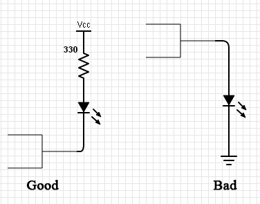
LEDs can be connected in two different configuration as shown in the diagram. In Good configuration LED is connected in sink mode with current limitting
resistor. When 0 is written to the port LED glows as current flow through the LED, Microcontroller then to the ground. LED goes off when 1 is written.
In Bad configuration LED glow when 1 is written and off when 0 is written. As TTL can source far less current than required by LED,
brightness will be less in Bad configuration, thats why we call it Bad.
When LEDs are connected in sinking mode it will get enough current and will be brighter. Resistor is required to limit the current flowing through the
LED, its value can be calculated by R = (5 – 1.7)/10mA = 330 Ohm as other end of resistor is connected to 5Vold.
To blink LED at regular interval, repeat the below 4 steps.
1.	Write zero to the port
2.	Delay
3.	Write one to the port
4.	Delay
In step 1 writing zero to the port switches on the LED, wait for some time, switch off by writing 1 and again wait for some more time.
Delay in step 2 & 4 can be achieved by looping through Pass statement number of times and it should be considerably large duration for
human to perceive the On and Off effect. Play with the delay time and settle at time which you feel optimal.
While adjusting the delay duration you would have observed LED glows at lower brightness, Don't panic nothing wrong happened to our hardware,
instead we learnt a new technique called Pulse Width Modulation.
When LED switch On/Off at very high rate human can not different the On/Off period instead see them as a whole, this makes our eye perceive
less brighter light than the actual brightness. The resulting brightness is depend on the duty cycle, it is the ratio of On time to On+Off time.
For example if LED glow for 1ms and off for 2 ms, our eye will see a light 1/(1+2)rd brighter than the actual.
Speaking to 8051
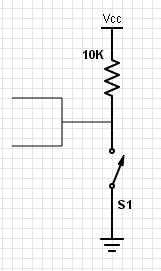
Circuit to interface switch is shown. To use the pin as input, initially logic 1 has to be written to the pin. When switch is open, microcontroller will read 1, when closed, pin will be tied to ground and it will read zero. Thus closer of switch gives logic zero. To know the status of the switch, program should poll the switch at regular interval or need to implement interrupt logic. Normally when switch is closed, contact will close and open frequently for 30 milliseconds. Opening of switch is one time transition from zero to one. This process is called debouncing. 30ms is large duration for microcontroller and it will read many transition from 1 to 0. This need to be handled else our program will malfunction. Buffer IC which suppresses any further transition after that first transesion can be used or simple resistor capacitor pair will also work. Microcontroller can debouncing through software method which is simple and avoids additional hardware.
1. Wait till pin becomes zero
2. Delay for 40/50milliseconds
3. If still pin is zero proceed with action else jump to step 1.
4. Action to be performed